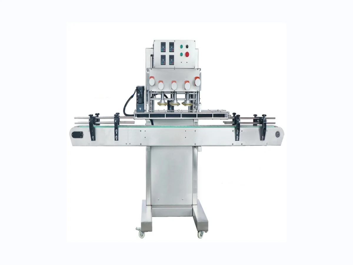
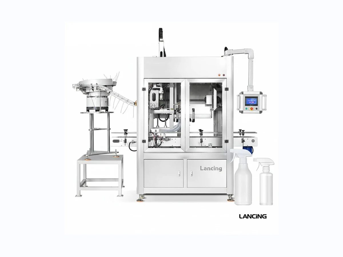
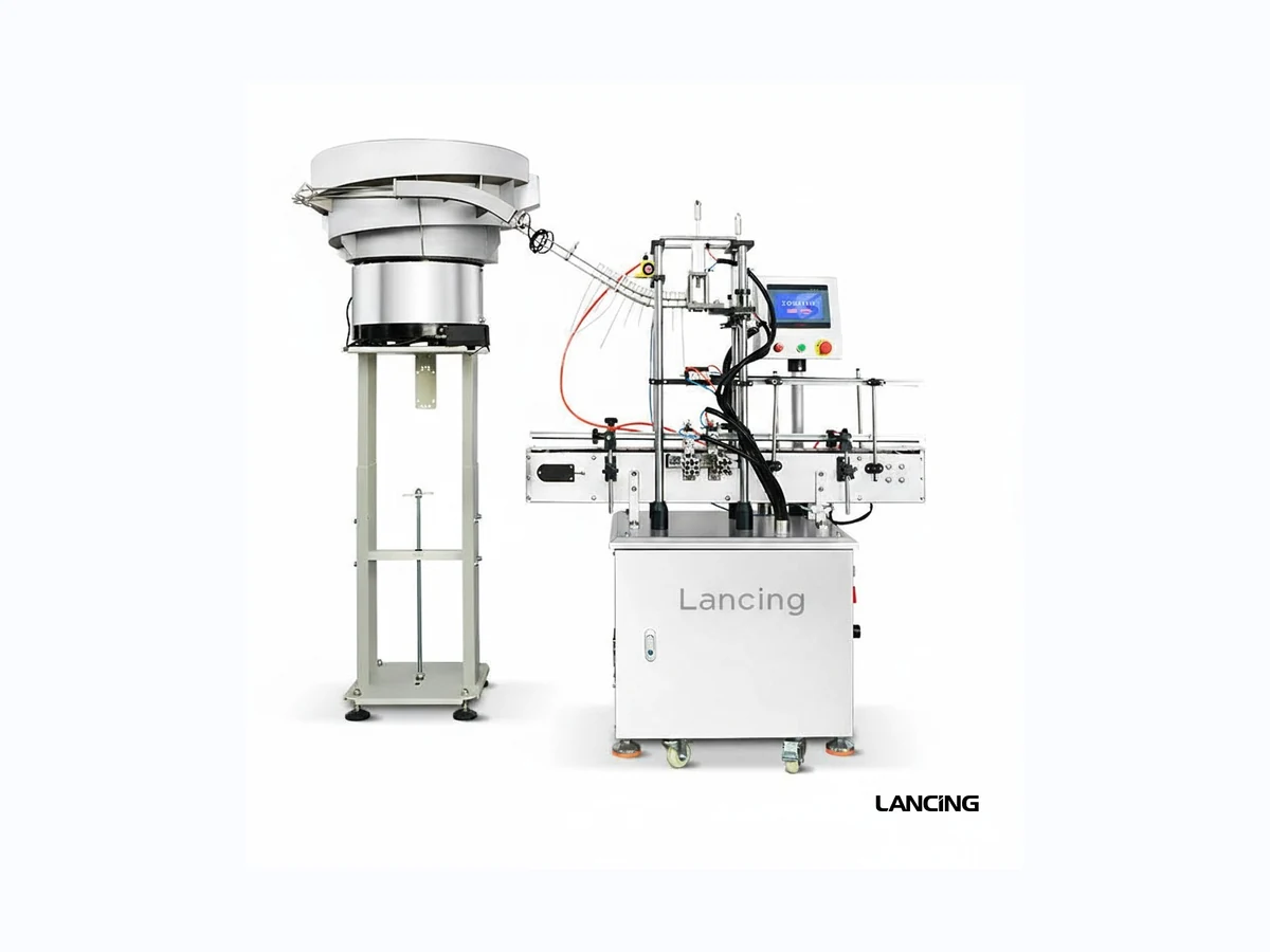
Automatic Belt Spindle Screw Capping Machine
High-speed inline spindle capper for round plastic bottles, with side-belt handling and optional cap elevator or vibratory bowl feed.
- Output
- 3,000–5,000 bottles/hour
- Cap
- Screw caps, material-dependent
Spindle and screw capping range
Compare the supplied Lancing capping machinery range, from compact desktop screw cappers through to automatic inline spindle cappers and trigger sprayer systems.
Selection first
Spindle capping machines can be an effective route for production lines that need repeatable screw-cap tightening. The correct configuration depends on the cap style, bottle stability, cap feed method, output target and how the capper connects with filling, labelling and outfeed equipment.
Use this page as the main machine range hub, then move into the product page or buyer guide that best matches the closure and output.
High-speed inline spindle capper for round plastic bottles, with side-belt handling and optional cap elevator or vibratory bowl feed.
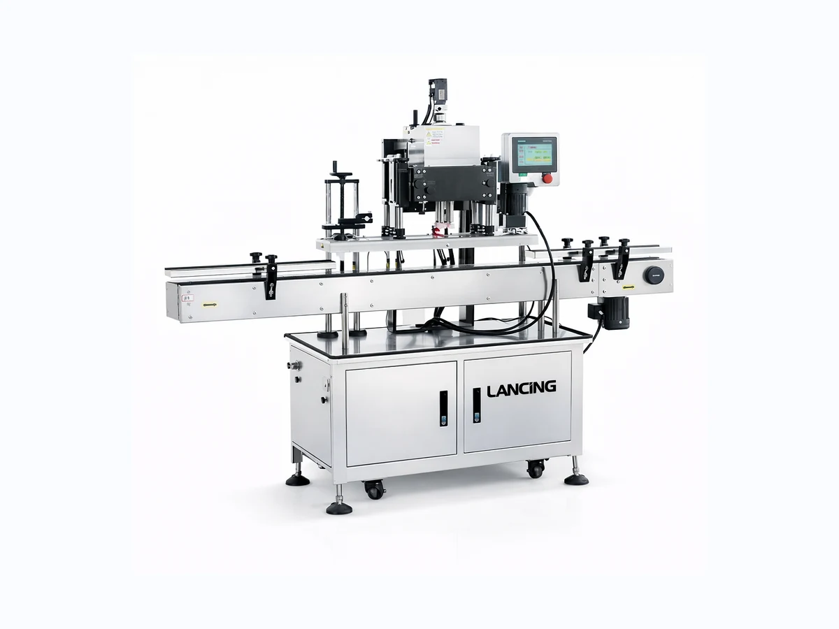
Pneumatic inline capping machine for sprays, pumps and screw caps where consistent torque, guide control and changeover flexibility matter.
Desktop semi-automatic capper with bottle clamping, manual/auto modes and stable torque control for lower-volume production.
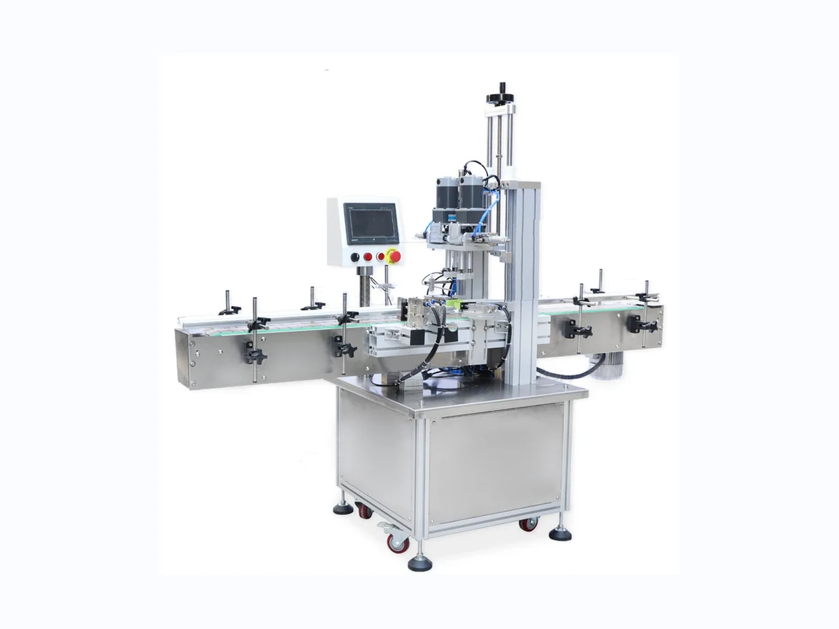
Space-saving compact capper for sprays and screw caps, designed for operations that need repeatable torque without a large automatic line.
Automatic trigger sprayer capping system for bottles where the closure, dip tube and bottle presentation all need to be controlled.
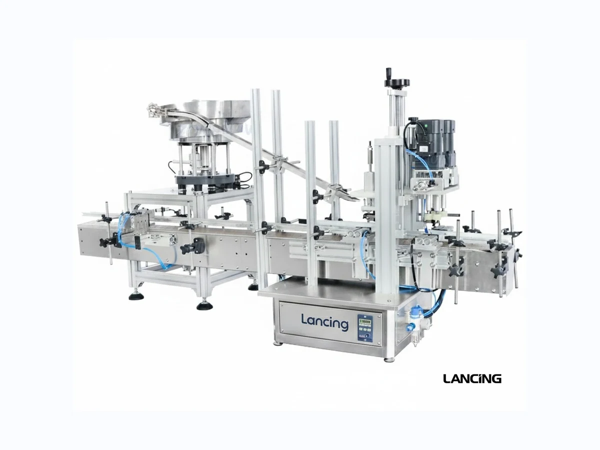
Cap feeding equipment for trigger spray caps with soft dip tubes, using vibratory sorting, conveyor handling and pneumatic placement support.
Comparison
| Machine | Typical output | Cap / closure | Best project fit |
|---|---|---|---|
| Automatic Belt Spindle Screw Capping Machine | 3,000–5,000 bottles/hour | Screw caps, material-dependent | High-speed automatic spindle capping for stable round plastic bottles. |
| Automatic Screw Capping Machine for Sprays, Pumps and Screw Caps | 20–60 bottles/min | Cap Ø 18–70 mm | Flexible inline capping for sprays, pumps and screw caps. |
| Semi Automatic Screw Capping Machine | Typical 20–60 bottles/min | Cap Ø 20–60 mm; up to 90 mm by custom option | Semi-automatic bench-top capping for lower-volume batches. |
| Compact Desktop Screw Capping Machine | Approx. 20–40 bottles/min | Cap Ø 18–70 mm | Compact repeatable torque control for limited production space. |
| Automatic Trigger Sprayer Capper | 1,200 BPH | Trigger sprayer, customizable | Automatic trigger sprayer capping where dip tube control matters. |
Decision route
Best for lower-volume work, flexible batches and projects where an operator can place the cap before tightening.
Best where output is sustained and the capper must work with conveyors, side belts and cap feed.
Best for pumps, triggers and closures with dip tubes or orientation issues that need project-specific handling.
Related pages
Ready to shortlist?
Lancing UK will help identify the most practical capping route and quote the right machinery scope.
Engineering selection
The base capper is only one part of a reliable automatic capping cell. The bottle must arrive at the correct spacing, the cap must be presented in the required orientation, thread engagement must begin cleanly, and the bottle must be held firmly enough for the progressive tightening stages.
In a typical belt or spindle arrangement, side belts stabilise and move the bottle through the capping station while pairs of spindle wheels contact the cap in sequence. Early contact can help seat and start the closure; later contact completes tightening. The exact number, material, pressure and position of contact elements are configuration decisions rather than universal settings.
Pre-threading quality is critical. If a cap enters at an angle, torque alone cannot correct the thread. Cap chute geometry, cap release timing, bottle spacing and the position of the first contact stage all influence whether the cap starts cleanly.
Round, stable bottles are generally the most straightforward. Tall, light, oval, square or flexible containers may need extended guides, different side-belt contact, neck support, format parts or a different technology. Labels and decoration must also be considered because the stabilising belts should not damage the finished pack.
Closure geometry affects both feeding and tightening. Tall caps, smooth caps, tamper-evident bands, liners, pumps and trigger sprayers can behave differently even where the nominal diameter is similar.
Specification matrix
| Evidence | Why it changes the design | Acceptance record |
|---|---|---|
| Bottle family | Diameter, height, rigidity, shape, fill weight and centre of gravity determine guide and belt support. | Empty and filled samples; smallest, largest and least stable formats identified. |
| Closure family | Thread, skirt, liner, tamper feature, external grip and surface finish affect cap start, contact and torque. | Production caps from normal supply, drawings where available and approved finished packs. |
| Cap presentation | Manual placement, elevator, bowl, chute or specialist handling changes labour, line rate and recovery behaviour. | Feed trial showing orientation, single-cap delivery, low-level response and restart after interruption. |
| Torque method | The practical target must protect the seal and user experience without damaging the pack. | Agreed sample method, removal-torque range or other closure-integrity checks, with defined sample size. |
| Sustained output | Usable output includes replenishment, normal operator tasks, line stops and downstream capacity. | Timed representative run with rejects, stops and causes recorded. |
| Changeover | Format spread determines adjustment range, setting aids, change parts and operator time. | Documented settings and repeat trial on the most different formats. |
Access and recovery should be reviewed for the hopper, bowl or elevator, track, chute, cap release point and capping zone. Recovery must not depend on unsafe reach-in or undocumented adjustments.
Operators and engineers need access to clean sensors, inspect belts and wheels, check guide security and remove product or cap debris without losing recorded settings.
Confirm start/stop signals, low-cap response, bottle backup detection, emergency-stop interfaces and how the capper behaves when the filler or labeller pauses.
Related planning pages
Review the published 3,000–5,000 bottles/hour range and side-belt configuration.
Review the flexible inline route for screw caps, pumps and sprays.
Compare manual placement, elevators, bowls, chutes and specialist handling.
Turn an undefined tightening requirement into practical acceptance evidence.
Plan checks for belts, wheels, guides, sensors and cap-feed components.
Identify bottle, cap, operator, guarding and integration risks before order.
Review the inline spindle route for continuous screw-cap tightening and line integration.
Frequently asked
The bottle must remain controlled while the closure starts and tightens. Shape, rigidity, filled weight, label position and centre of gravity all influence the side-belt and guide arrangement.
Contact surfaces are selected around the bottle and cap materials, required grip, cosmetic finish and torque method. Real samples are needed to check scuffing, slip and repeatability.
Some inline routes can handle them, but dip tubes, head orientation and cap presentation may require specialist feeding or a different capping head.
Record where the jam starts, whether it is detected, how safely it can be cleared, the restart sequence and whether the feeder returns to single, correctly orientated caps.
Use the pack-specific acceptance method, such as removal torque, leak checks, cap height, visual thread engagement, liner seating and approved opening performance.
A chuck or single-head system may be preferable for low volumes, difficult closures, precise individual head control or packs that cannot be stabilised through progressive spindle contact.
Specification support
Include representative bottle and closure samples, the required output, any known torque or closure-integrity checks, the cap presentation method and photographs of the proposed line area.
Continuous capping decision
An inline spindle capper is strongest when bottle flow, cap presentation and progressive tightening can be controlled as one continuous process. The decision should be based on evidence from the complete pack and line rather than the machine name alone.
A stable bottle must enter at a predictable spacing, remain controlled between the guide and gripper belts, and carry a cap that can be placed squarely before the main spindle stages. The closure needs enough usable external contact for the wheels to grip without unacceptable marking, while the bottle must resist rotation without being crushed or scuffed.
The process also has to fit the wider line. Upstream filling must deliver bottles in a condition the capper can handle, and downstream equipment must accept the finished packs without creating repeated backup through the tightening zone.
Investigate another capping method when a bottle cannot be stabilised, a closure cannot be pre-threaded consistently, cosmetic limits prevent suitable wheel contact, or one-at-a-time tooling is required for a difficult cap. Pumps, trigger sprayers and asymmetric closures may need specialist orientation and placement before tightening.
Short batches can also favour an operator-assisted or chuck route when automatic feeding and continuous bottle handling would add more complexity than value. Use the wider Lancing screw-capping resource where the main decision is between bench, chuck and general screw-cap systems rather than an inline spindle process.
Decision evidence
| Evidence area | Why it changes the spindle-capper decision | What to retain for quotation and FAT |
|---|---|---|
| Bottle path | Height, width, rigidity, centre of gravity, fill weight and decoration determine guide and belt contact. | Empty and representative filled samples, including the least stable format and photographs of existing handling. |
| Cap start | Thread form, skirt, liner, tamper feature and initial placement decide whether the closure enters squarely before tightening. | Production caps from normal supply, approved finished packs and examples of known thread or seating faults where available. |
| Spindle contact | Cap height, ribs, finish and stiffness affect grip, staged wheel position and the risk of cosmetic marking. | Accepted visual standard, cap drawings where available and trial photographs before and after capping. |
| Cap supply | Manual placement, elevator, bowl, chute or specialist placement changes labour, line rate and recovery behaviour. | Required orientation, normal replenishment method, low-cap response and the agreed recovery check after an interruption. |
| Quality method | A torque setting alone does not prove thread engagement, liner seating, leakage control or opening experience. | Approved packs and the agreed cap torque and closure-integrity method. |
| Line balance | Nominal capper speed is only useful when filling, bottle spacing, cap replenishment and downstream transfer remain stable. | Required sustained output, line sequence, available accumulation and the conditions to be represented during the trial. |

For every approved bottle and cap combination, record machine height, guide positions, gripper-belt gap, spindle-wheel positions, conveyor speed, cap-feed settings and the first-off checks used to release production. A repeatable format record is more useful than a one-off successful run because it supports future changeovers, maintenance and fault finding.
From selection to stable production
Turn a broad requirement for an automatic spindle capper or inline screw capper into a testable brief covering the complete closure process.
| Stage | Project question | Next resource |
|---|---|---|
| Bottle transport | Can the filled bottle enter and pass the gripper belts without spin, scuffing or distortion? | Bottle stability |
| Cap presentation | Can the cap be oriented, released and started squarely? | Cap chute and pre-threading |
| Tightening | Can progressive contact reach an accepted result without damage? | Setup checklist |
| Pack acceptance | Which visual, torque or integrity checks define approval? | Quality control plan |
| Line integration | How does the system respond to starvation, faults and blockage? | Line balancing |
| Handover | Which settings, training and maintenance records remain with the machine? | Commissioning |
Process questions
These issues often decide whether an apparently suitable spindle capper produces an acceptable pack consistently in real production.
Cap marking can originate in the feeder, chute, spindle wheels or contact between an unstable bottle and the guides. The key is to locate where the first mark appears and determine whether the cap is rolling through controlled contact or sliding under excess pressure. The cap-scuffing diagnostic guide provides a fault-isolation sequence.
A cap can appear correctly tightened but later relax because of incomplete thread engagement, liner compression, cap or neck variation, product contamination, pack temperature or an unsuitable acceptance method. Compare cap height, thread start, removal torque and closure integrity over an agreed interval. See what causes caps to loosen after capping.
The restart sequence should prevent uncapped bottles, doubled caps and trapped closures from entering the tightening zone. Define how the line stops, which bottles are held or removed, how the feeder and chute are checked, and which first-off packs are inspected before normal speed resumes. The cap-feed recovery guide explains the evidence to capture.
Inspect the closure around its full circumference against an approved bottle-and-cap datum, not only from one camera angle. A tilted cap can indicate an uneven thread start, trapped liner, damaged neck, tamper-band interference or unstable bottle presentation. The cap-height inspection guide compares manual, sensor and vision checks.