
Automatic screw capper
Automatic Screw Capping Machine for Sprays, Pumps and Screw Caps
Pneumatic inline capping machine for sprays, pumps and screw caps where consistent torque, guide control and changeover flexibility matter.
- Output
- 20–60 bottles/min
- Cap
- Cap Ø 18–70 mm
- Container
- Bottle Ø 20–160 mm; height 30–300 mm
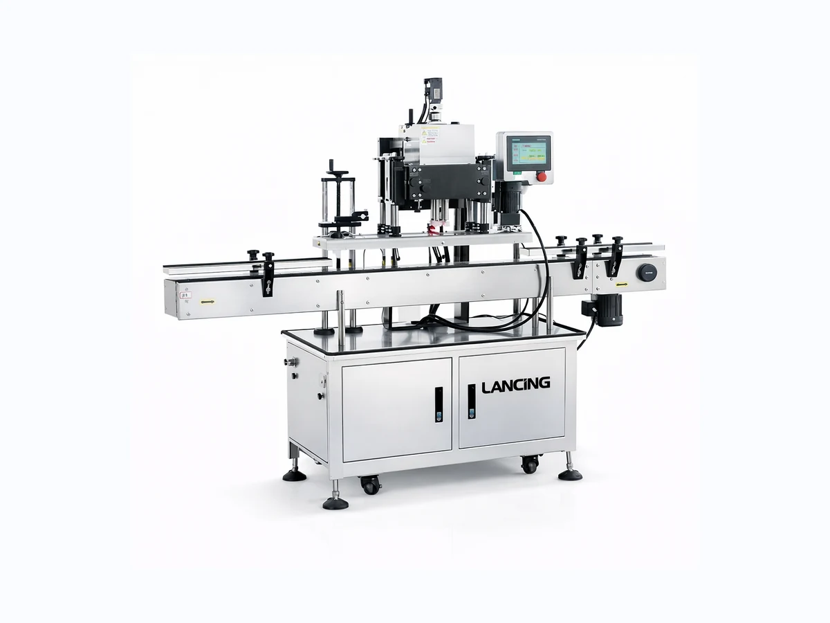
Machine overview
Where this capper fits
Pneumatic inline capping machine for sprays, pumps and screw caps where consistent torque, guide control and changeover flexibility matter.
- Inline capping station for repeatable tightening on stable bottles.
- Guide and clamp setup can be adapted for different bottle families.
- Useful where sprays, pumps or screw closures are part of the same project.
- Can be planned as a stand-alone capping unit or part of a wider filling, capping and labelling line.
Technical specifications
| Output | 20–60 bottles/min, cap and bottle dependent |
|---|---|
| Cap diameter | 18–70 mm |
| Bottle diameter | 20–160 mm |
| Bottle height | 30–300 mm |
| Closure types | Sprays, pumps and screw caps |
See capping in context
Plan the complete capping cell, not only the base machine.
For reliable production, the capping unit should be matched to bottle stability, cap feed, changeover frequency, torque expectation and the wider line layout.
Send your bottle and cap detailsApplications
Typical uses
Enquiry checklist
Information to send for this machine.
The fastest way to confirm suitability is to send clear product, bottle and closure information with the expected output and available line space.
- Photos or samples of the bottle and cap.
- Target output in bottles/min or bottles/hour.
- Cap torque requirement or current acceptable torque range.
- Whether caps will be manually placed or automatically fed.
- Available space, conveyor details and downstream equipment.
Talk to Lancing UK
Check whether this capper is the right fit.
Send the machine name, bottle details, cap details and target output. We will come back with the best route and configuration.
Flexible inline capping
Specify the inline screw capper around pumps, sprays and threaded closures.
The published range covers a broad mix of bottle sizes and cap diameters. That flexibility is useful, but pumps and trigger sprayers introduce presentation, dip-tube and orientation requirements that should be treated as part of the capping system.
Selection and operating method
The machine is described as a pneumatic inline capping route with adjustable guides and clamp control. For standard screw caps the focus is clean thread engagement and repeatable tightening; for pumps and sprays the cap must also arrive at the bottle without tube interference or head misorientation.
Format records should identify bottle guides, clamp or holding settings, head height, cap tooling, conveyor speed and any cap-feed adjustments. Components that contact the closure or bottle should be kept clean and inspected for wear.
Changeover, maintenance and line integration
Pumps and trigger sprayers should be checked for tube snagging and orientation during both normal running and restart. A stable cap handover is often more important than the nominal tightening cycle.
For integrated lines, agree the machine response to upstream starvation, downstream backup, low cap level and emergency stops, including the state of bottles already inside the capping zone.
Published data and test conditions
Use the stated range as a starting point for sample validation.
Values are retained from the supplied first-party product page. They are not a guarantee for every closure or bottle; the representative production pack and agreed acceptance method determine the final configuration.
| Published output | 20–60 bottles/min, dependent on the cap and bottle. |
|---|---|
| Cap diameter | 18–70 mm. |
| Bottle diameter | 20–160 mm. |
| Bottle height | 30–300 mm. |
| Closure types | Sprays, pumps and screw caps. |
| Torque condition | Consistent torque is a project aim; no numerical torque range is published and sample validation is required. |
Trial and acceptance evidence
Checks that establish usable performance.
Closure presentation
Test standard caps, pumps and sprays separately. Record cap angle, tube position and whether the closure reaches the thread cleanly.
Guide and clamp control
Use the lightest and tallest filled bottles to check movement, clamp marking and repeatability at the required line rate.
Torque repeatability
Measure the agreed removal-torque or integrity criteria after the pack leaves the capping station, not only at the head.
Changeover proof
Run the most different bottle and cap formats and confirm which guides, tooling or settings change.
Stop and restart
Create a controlled bottle backup or cap shortage and verify safe recovery without double capping or uncontrolled release.
Line interface
Confirm spacing and signals with filling, conveying, labelling and outfeed equipment.
When another technology may be more suitable
A specialist trigger or pump capping system may be preferable where dip tubes, head orientation or cap presentation dominate the project. A semi-automatic capper may be more practical for low-volume, highly variable work.
Related pages
- Trigger sprayer capper — Review the automatic trigger-specific route.
- Trigger cap feeder — Review bowl sorting and dip-tube handling.
- Bottle stability guide — Prepare filled samples and guide checks.
- Capping risk assessment — Plan safe access, recovery and line interfaces.
- Trigger capping specialist — Use for detailed trigger-closure ownership and handling routes.
Buyer questions
Questions to resolve before final specification.
Can one machine run screw caps, pumps and sprays?
The published page lists all three closure groups, but each format requires sample confirmation and may need different tooling, guides or feed handling.
What limits the 20–60 bottles/min range?
Cap presentation, bottle stability, closure behaviour, operator tasks and line conditions determine the sustained rate.
Are dip tubes part of the trial?
Yes. Use production-length tubes and filled bottles because tube flexibility and product weight can change handling.
Can caps be manually placed?
The cap presentation route should be agreed for the required output. Manual placement may suit lower rates; automatic feeding requires closure-specific testing.
How should a restart be tested?
Pause the cap or bottle supply, clear the condition safely and confirm that the first restarted packs are correctly capped without doubles or mis-threading.
What information helps quotation accuracy?
Send bottle and closure samples, filled weight, target output, torque or integrity criteria, cap-feed preference and the surrounding line layout.
Specification support
Send representative samples for a configuration review.
Include representative bottle and closure samples, the required output, any known torque or closure-integrity checks, the cap presentation method and photographs of the proposed line area.
Representative material trial
Test sprays, pumps and screw caps as separate closure families.
The published range covers 20–60 bottles/min subject to cap and bottle behaviour, cap diameters of 18–70 mm, bottle diameters of 20–160 mm and heights of 30–300 mm. A pump, trigger or standard cap can fit those dimensions but still need different placement and control.
| Closure | Trial focus | Evidence |
|---|---|---|
| Screw cap | Orientation, square start, liner behaviour and tightening. | Cap and neck drawings, samples and acceptance method. |
| Pump | Dip-tube entry, head orientation, stability and marking. | Loose parts, assembled samples and final direction. |
| Trigger | Long dip-tube handling, trigger orientation and placement. | Representative triggers, filled bottles and final direction. |
Inline screw capping questions
Checks before specifying pumps, sprays or screw caps
What causes cross-threading on an inline capper?
Cross-threading usually begins at cap handover, pre-threading or bottle control. Reducing torque alone will not solve a cap that starts at an angle or binds on the wrong thread.
Why measure cap height?
Cap height shows whether the closure reached a repeatable position. It helps distinguish poor thread start, liner variation, cap tilt and over-tightening from a simple machine-speed issue.
Which samples are needed?
Include spray heads, pump dip tubes, screw caps, filled bottles and difficult formats so the capping method can be checked against the real closure behaviour.