
Automatic spindle capper
Automatic Belt Spindle Screw Capping Machine
High-speed inline spindle capper for round plastic bottles, with side-belt handling and optional cap elevator or vibratory bowl feed.
- Output
- 3,000–5,000 bottles/hour
- Cap
- Screw caps, material-dependent
- Container
- Bottle Ø 35–120 mm; height 60–200 mm
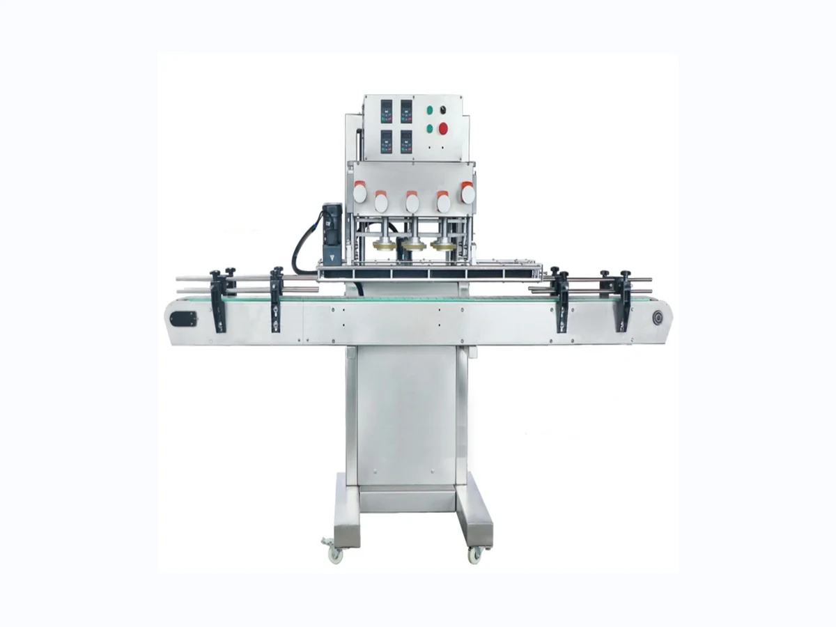
Machine overview
Where this capper fits
High-speed inline spindle capper for round plastic bottles, with side-belt handling and optional cap elevator or vibratory bowl feed.
- Side-belt transport keeps bottles controlled through the tightening area.
- Multiple spindle wheels progressively tighten the closure for stable torque.
- Cap feed options can be matched to the cap geometry, line speed and operator workflow.
- Inline layout suits integration after filling and before labelling.
Technical specifications
| Output | 3,000–5,000 bottles/hour, subject to cap and bottle behaviour |
|---|---|
| Bottle range | Diameter 35–120 mm; height 60–200 mm |
| Cap feeding | Optional cap elevator or vibratory bowl feeder |
| Capping heads | Quantity configurable to required capacity |
| Best suited to | Cleaners, oils, chemicals, household products and speciality liquids |
See capping in context
Plan the complete capping cell, not only the base machine.
For reliable production, the capping unit should be matched to bottle stability, cap feed, changeover frequency, torque expectation and the wider line layout.
Send your bottle and cap detailsApplications
Typical uses
Enquiry checklist
Information to send for this machine.
The fastest way to confirm suitability is to send clear product, bottle and closure information with the expected output and available line space.
- Photos or samples of the bottle and cap.
- Target output in bottles/min or bottles/hour.
- Cap torque requirement or current acceptable torque range.
- Whether caps will be manually placed or automatically fed.
- Available space, conveyor details and downstream equipment.
Talk to Lancing UK
Check whether this capper is the right fit.
Send the machine name, bottle details, cap details and target output. We will come back with the best route and configuration.
Automatic spindle capping
Validate the automatic belt spindle capper with the real production pack.
This route is intended for continuous screw-cap tightening on bottles that can be controlled by an inline conveyor, guides and side belts. The published operating envelope supports a useful shortlist, but it does not replace a trial with production caps and filled bottles.
Selection and operating method
Side belts hold and transport the bottle while successive spindle wheels contact and tighten the closure. The progressive arrangement can support continuous flow, but clean pre-threading and consistent cap presentation must be established before final torque is applied.
Because the side belts and wheels are pack-contact components, changeover records should include belt gap, guide position, machine height, spindle-wheel position and conveyor speed. Contact surfaces should be inspected for wear or contamination that could change grip or mark the pack.
Changeover, maintenance and line integration
Integration checks should cover conveyor height, bottle spacing, cap-feed interface, low-cap response, bottle backup and stop/start behaviour with filling and labelling equipment.
Critical spare planning should reflect operating hours and downtime tolerance, with attention to belts, spindle wheels, sensors, guide components, bearings and pneumatic fittings.
Published data and test conditions
Use the stated range as a starting point for sample validation.
Values are retained from the supplied first-party product page. They are not a guarantee for every closure or bottle; the representative production pack and agreed acceptance method determine the final configuration.
| Published output | 3,000–5,000 bottles/hour, subject to cap and bottle behaviour. |
|---|---|
| Published bottle range | Diameter 35–120 mm; height 60–200 mm. |
| Closure route | Screw caps; suitability is material and geometry dependent. |
| Bottle control | Side-belt transport through the tightening area. |
| Cap feed options | Optional cap elevator or vibratory bowl feeder. |
| Capping stages | Spindle-head quantity configured to the required capacity; no numerical torque window is published. |
Trial and acceptance evidence
Checks that establish usable performance.
Thread start
Confirm that caps enter squarely and start the bottle thread before the final spindle stages. Record cross-threading and skewed caps.
Bottle stability
Run the least stable filled bottle and inspect twisting, tilting, belt marks, label disturbance and conveyor hesitation.
Torque and seal
Use the project-specific removal-torque or closure-integrity method over an agreed sample set; include leakage and cap damage.
Cap-feed recovery
Interrupt the elevator or bowl supply, then record detection, safe clearing and return to single-cap delivery.
Sustained output
Time a representative run including cap replenishment, normal operator work and downstream interaction.
Format repeatability
Change between the smallest and largest agreed formats, record settings and verify that the first-off packs meet acceptance checks.
When another technology may be more suitable
A chuck capper or semi-automatic route may be better for short runs, difficult individual closures, very unstable bottles or projects that need one-at-a-time head control. Pumps, trigger sprayers and closures with orientation features may also need specialist feeding rather than a standard cap chute.
Related pages
- Cap feeding systems — Compare elevators, bowls, chutes and recovery planning.
- Bottle stability guide — Plan side-belt contact and filled-sample tests.
- Torque test method — Define measurable closure acceptance.
- Maintenance schedule — Inspect belts, wheels, guides and sensors.
- Screw capping specialist — Use for wider screw-cap machine and chuck-capper routes.
Buyer questions
Questions to resolve before final specification.
Is 3,000–5,000 bottles/hour guaranteed?
No. The supplied page states that output is subject to cap and bottle behaviour. Sustained output should be demonstrated with the agreed pack and line conditions.
Why are side belts important?
They resist bottle rotation and keep the pack controlled while spindle wheels tighten the cap.
Can the machine use a bowl feeder?
An optional cap elevator or vibratory bowl feeder is listed, but the closure must be tested for reliable orientation and handover.
How is torque set?
No universal numerical torque is published. Use closure guidance, approved packs and a representative machine trial to agree the practical acceptance range.
What bottles are highest risk?
Tall, light, flexible, tapered or decorated bottles may need additional support or a different contact arrangement.
What should be recorded at changeover?
Record height, guides, side-belt gap, spindle positions, conveyor speed, cap-feed settings and the first-off quality checks.
Specification support
Send representative samples for a configuration review.
Include representative bottle and closure samples, the required output, any known torque or closure-integrity checks, the cap presentation method and photographs of the proposed line area.
Restart and recovery trial
Prove restart behaviour as well as steady running.
The published 3,000–5,000 bottles/hour range is subject to cap and bottle behaviour. A useful machine trial should therefore show what happens when normal production is interrupted, not only when compatible samples are already flowing cleanly.
| Deliberate trial condition | Evidence to record | Practical acceptance point |
|---|---|---|
| Cap supply is reduced or stopped | Low-cap or empty-track response, bottle control, operator warning and whether uncapped bottles reach the tightening zone. | The agreed stop or hold action occurs without uncontrolled bottles or repeated manual correction. |
| One cap is skewed or poorly presented | Where the fault is detected, whether the cap enters the spindle stages and the safe clearing method. | The fault can be identified and cleared without bypassing guards or leaving an uncertain pack in the line. |
| Downstream equipment creates bottle backup | Queue sensing, side-belt behaviour, bottle contact and the condition of caps held in or near the capping station. | Bottles remain controlled and restart without double handling, thread damage or a burst of rejects. |
| The line stops during tightening | Position of bottles and caps, restart sequence, first packs after restart and any torque or appearance change. | The first-off packs after restart meet the same closure and visual checks as steady production. |
| Smallest and largest agreed formats are changed | Recorded guide, height, belt, spindle, conveyor and feeder settings plus the correction needed after first-off inspection. | The documented setup can be reproduced without relying on an individual operator's memory. |
| Representative run includes normal operator work | Cap replenishment, routine checks, minor stops, downstream interaction and cause-coded lost time. | Sustained output is reported with the actual trial conditions, rather than as an isolated peak cycle. |
Commissioning evidence pack
Retain the bottle and cap batch identity, filled weight or product substitute, approved reference packs, machine settings, cap-feed method and the acceptance results. A short cause-coded stop log is valuable because it separates cap presentation, bottle handling, spindle contact, downstream backup and operator intervention.
Photographs or video can support the record, but they should show the complete bottle path and cap handover rather than only the final tightening stage. The supplied machine footage on this page is useful for understanding the arrangement; final approval still requires representative production samples.
Connect the capper to the line controls
Confirm how the capper responds to upstream gaps, downstream backup, low cap level and an empty chute. Agree which system controls each stop condition and what an operator must check before restart. Where automatic cap presentation is part of the project, use the cap-feeding systems guide for the capper interface and the specialist Lancing cap-feeder resource for detailed feeder selection.
Use the FAT checklist to define the test record and the troubleshooting guide to classify any faults without masking them by increasing pressure or torque.
Model trial record
Validate the published range against the real bottle and cap family.
The published route covers 3,000–5,000 bottles/hour subject to cap and bottle behaviour, bottle diameters of 35–120 mm and heights of 60–200 mm. Final suitability still depends on filled-bottle stability, cap presentation, thread start and the agreed finished-pack checks.
| Trial item | Condition to record | Purpose |
|---|---|---|
| Representative bottle | Diameter, height, fill level, material, rigidity and centre of gravity. | Confirms guide and side-belt control. |
| Production closure | Supplier, batch, dimensions, thread, liner and tamper features. | Tests feed, pre-thread and contact behaviour. |
| Cap presentation | Manual, elevator or bowl route, chute and demand control. | Separates feeder limits from tightening performance. |
| Pack acceptance | Visual seating, defined torque and integrity checks. | Prevents output alone being treated as proof. |
| Line states | Steady run, starved infeed, blocked discharge and restart. | Shows complete-line recovery. |
Operating evidence
Questions about bottle grip, recovery and usable output
An automatic belt spindle capper should be assessed as a continuous handling process, including the conditions that cause slips, stops and rejected packs.
Can gripper belts damage or deform lightweight bottles?
Yes, a flexible or thin-walled bottle can distort if the belt gap, belt contact height or guide position applies unsuitable pressure. The same bottle may behave differently when filled because weight and internal support change. Trial the lightest and least stable filled format, observe sidewall and neck deflection, and confirm that the bottle remains controlled without visible damage or label disturbance.
How do you distinguish bottle slip from insufficient spindle-wheel grip?
Bottle slip usually shows rotation, hesitation or inconsistent travel at the side belts, while insufficient closure grip shows the cap failing to advance despite stable bottle movement. Marking the bottle and cap for a controlled observation can help locate the relative movement. Check bottle stability, belt condition and guide alignment before increasing spindle-wheel pressure, because extra cap pressure can hide the real handling fault.
What should be checked after an emergency stop or downstream backup?
Check the bottles and caps already inside the capper, the state of the cap chute, belt and conveyor positions, and whether any closure has been partly started or tightened twice. Define which packs are removed, which sensors must be reset and how first-off bottles are inspected. A controlled restart should be included in the line test, not left until production.
How should sustained production output be demonstrated?
Demonstrate output over a representative run that includes normal cap replenishment, operator tasks, upstream spacing, downstream accumulation, routine quality checks and at least one planned stop-and-restart. Record accepted bottles rather than theoretical cycles. The run should use representative filled packs and the agreed cap supply method so the result reflects the complete production process.
Trial evidence
Extra checks for automatic belt spindle cappers
How do you prove bottle stability at speed?
Run the lightest and most unstable filled formats, then record whether side belts hold the bottle without spin, tilt, scuffing or loss of thread engagement through stop/start conditions.
Why check conveyor transfer points?
The capper depends on stable infeed and discharge. Poor transfers can alter pitch, create bottle pressure or disturb freshly capped containers before inspection and labelling.
What counts as usable output?
Usable output is the rate achieved with acceptable cap height, torque evidence, closure integrity and controlled recovery, not only the fastest short burst through the conveyor.