
Cap feeding and orientation
Cap feeding systems for capping machines
Cap feeding systems, cap elevators and bowl-feeder routes for capping projects where manual cap placement limits output or consistency.
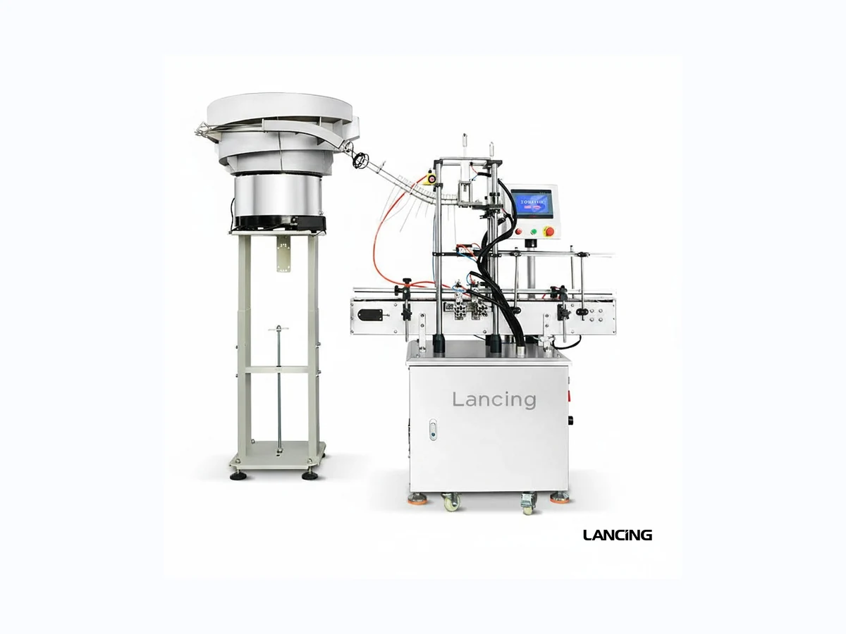
Feed route
Choose cap feeding by cap shape, orientation and line speed.
Cap feeding is often where automatic capping projects succeed or fail. A cap that looks simple by hand may be difficult to orient at speed, particularly if the closure is lightweight, tall, handled by a dip tube or supplied with inconsistent geometry.
Lancing UK can review whether caps should be manually placed, elevator-fed, chute-fed, bowl-fed or handled with a more project-specific feed system.
Feed details to send
- Cap photos, drawings or physical samples.
- Cap diameter, height, weight and orientation needs.
- Required bottles per minute and capper type.
- Whether caps arrive loose, nested, bagged or pre-sorted.
- Available floor space, height and operator access.
Comparison
Common cap feeding routes
| Feed route | Best use | Checks needed |
|---|---|---|
| Manual cap placement | Short runs, low output and high product variation. | Operator workload, torque repeatability and safety. |
| Cap elevator | Higher output where caps can be lifted and presented consistently. | Cap style, hopper size, chute route and capper interface. |
| Vibratory bowl feeder | Caps that can be sorted and oriented by vibration and tooling. | Cap geometry, noise, footprint, orientation and changeover parts. |
| Project-specific handling | Trigger sprayers, pumps, soft dip tubes and awkward closures. | Samples, test handling and realistic output expectations. |
Related routes
Connect cap feeding to the right capper
Ready to shortlist?
Send the bottle, cap and target output.
Lancing UK will help identify the most practical capping route and quote the right machinery scope.
Cap feeding evidence
Specify orientation, buffer capacity and recovery at the capper handover point.
A cap feeder should not be selected as an isolated hopper. It has to supply the downstream capper at a stable rate, present each closure in the correct orientation, manage recirculation and recover predictably when either the cap supply or production line is interrupted.
Match the route to the closure
Regular screw caps may suit an elevator and chute when their geometry allows consistent presentation. A vibratory bowl can sort caps through custom track tooling. Pumps, trigger sprayers and dip tubes may need grippers, straightening or project-specific handling. Manual placement remains a valid option where batches are short and output is modest.
Cap diameter alone does not establish feedability. Height, weight distribution, skirt profile, tamper band, liner, surface finish, static, tendency to nest and the required exit orientation all influence the design.
Recovery conditions to demonstrate
- Low cap level and normal replenishment.
- Inverted, doubled or damaged closure in the track.
- Capper stop while the feeder remains full.
- Downstream bottle backup or upstream starvation.
- Safe operator access and controlled clearing.
- Stable single-cap presentation after restart.
| Feed route | Best use | Evidence to request |
|---|---|---|
| Manual placement | Short batches, high format variation and lower output. | Timed operator cycle, ergonomics and sustainable placement rate. |
| Cap elevator and chute | Closures that can be lifted, sorted and delivered by gravity. | Orientation, chute fill, cap release, low-level response and handover to the bottle. |
| Vibratory bowl | Caps that can be separated and orientated with custom track tooling. | Normal production samples, recirculation behaviour, wrong-way rejection, noise and changeover parts. |
| Specialist pump or trigger handling | Irregular heads, tubes and closures that cannot use a standard chute. | Tube control, gripper timing, head orientation, placement accuracy and jam recovery. |
Connected pages
Keep feed design connected to the capper and pack.
Automatic spindle capper
Plan the feeder handover, side belts and sustained capping demand.
Trigger cap feeder
Review the LU-XG446S trigger and dip-tube route.
Cap sorting bowl versus elevator
Compare the main feed principles and sample needs.
Capping risk assessment
Review jams, operator access and control interfaces.
Cap feeder specialist site
Use for deeper feeder, bowl, elevator and singulation content.
General capping selection
Use for closure families beyond spindle capping.
Questions
Cap feeder specification questions.
Which cap feeding method is best for a spindle capper?
It depends on closure geometry, orientation, output, available height and how the cap must be handed to the bottle. Real cap samples are needed.
What is cap-feed recovery?
It is the feeder’s ability to detect and recover from low level, an inverted cap, a jam or a downstream stop without repeated manual adjustment.
Can a vibratory bowl feed every cap?
No. Some closures nest, tangle, scuff or cannot be orientated reliably by vibration. Sample-led tooling is essential.
When is manual cap placement acceptable?
Manual placement can be practical for short runs, frequent format changes or low output where operator workload remains acceptable.
How is feeder capacity specified?
The feeder must provide a stable rate above the capper’s sustained demand while allowing for recirculation, normal variation and recovery.
What information is needed for a feeder quotation?
Send caps from normal production supply, dimensions, material, required orientation, target rate, capper interface height and site photographs.
Specification support
Send cap samples and the downstream capper details.
Include representative bottle and closure samples, the required output, any known torque or closure-integrity checks, the cap presentation method and photographs of the proposed line area.
Capper interface
Define the handover and recovery sequence before selecting the feeder.
A cap feeder is not complete when caps leave a bowl or elevator. The feed path must deliver one correctly presented closure to the point where the bottle and capper can accept it, then respond predictably when either side of the interface stops.
| Interface state | Required behaviour to define | Evidence for the machine trial |
|---|---|---|
| Normal cap supply | Correct orientation, controlled spacing, adequate buffer and clean transfer into the chute or placement point. | Representative caps from normal supply run over a sustained period with wrong-way, double and gap events recorded. |
| Low bulk level | Warning, refill access and continued operation for the agreed buffer condition without flooding the track after replenishment. | Operator refill demonstrated using the expected container or hopper-loading method. |
| Empty chute or track | Capper and bottle-flow response when no closure is available at the handover point. | Controlled starvation test showing the stop, hold or reject action and the first packs after supply returns. |
| Wrong-way or doubled closure | Rejection, correction or safe stop before the closure reaches a position where it can damage tooling or create an uncertain pack. | Observed response using realistic fault examples where this can be done safely and without damaging parts. |
| Capper stopped or downstream blocked | Feeder output pauses before the chute overfills, caps bridge or excessive pressure builds at the handover. | Stop signal, buffer behaviour and restart sequence recorded with bottles present at the capper. |
| Restart after clearing | Return to single-cap delivery without a surge, double feed or series of poorly placed caps. | First-off closure checks, fault cause and any operator confirmation required before production resumes. |
Rate the complete feed path
A headline feeder rate is not the same as usable supply at the capper. The practical result depends on bulk loading, separation, orientation, reject tooling, track geometry, chute angle, buffer control, bottle spacing and the capper's own cycle. Test the complete route with the downstream machine and report the conditions used.
Include cap batch variation where available. Small changes in moulding, liner, tamper band, surface finish or static behaviour can alter nesting, bridging and scuffing even when the nominal dimensions are unchanged.
Keep the subject ownership clear
This page covers the interface between cap presentation and spindle capping. Detailed bowl, elevator, sorter and singulation design belongs on the dedicated Cap Feeders UK resource. The wider spindle-capping range remains the correct route when bottle control, tightening method and line integration are the main decision.
For acceptance, connect the feed-recovery test to the capping-machine FAT checklist and retain a settings record for every approved cap family and changeover.
Handover and recovery
Specify the feeder, chute and capper as one closure-handling system.
Orientation is only the first step. The project must also control single-file travel, chute demand, release timing and response to an empty chute, blocked cap or downstream stop.
Demand control
Confirm how low-cap and full-chute signals control the feeder without repeated surges.
Controlled handover
Observe the cap through release and square placement on the bottle.
Jam recovery
Define detection, safe isolation, authorised clearance and restart.
Feed reliability
Questions that expose cap-feeding risk before production
A feeder must do more than orient a short sample. It must maintain controlled handover, recover from interruptions and protect the capper from incorrect closures.
Why can a cap feeder run well for a short test and jam later?
A short test may not expose cap-to-cap nesting, dust, mixed batches, replenishment effects, chute back-pressure or the range of orientations created by a full hopper. Use normal production caps and run long enough to include replenishment and low-level conditions. If faults recur, record the exact cap batch, location and orientation rather than adjusting several feeder settings together.
What should happen to bottles already under the chute when cap supply stops?
The control sequence should identify bottles that have not received a cap, prevent them entering the tightening zone and define whether they are held, rejected or removed manually. Bottles with partly presented caps also need a clear disposition. The answer depends on the line layout, but it must be agreed and demonstrated before handover rather than left to operator improvisation.
How should inverted, doubled or damaged caps be handled before tightening?
The feed path should reject or stop on closures that cannot be presented in the approved orientation. Detection may be mechanical, sensor-based or vision-based depending on the cap, but the failure response must prevent a bad cap from reaching the spindle wheels. Confirm how the rejected closure is contained and how the feeder restarts without sending another incorrect cap.
What information should be recorded after a cap-feed fault?
Record the fault location, cap orientation, cap and bottle batch, hopper level, chute condition, line state, sensor indication, intervention and affected packs. Photographs of the cap before it is cleared can be more useful than a description after the evidence has been disturbed. Use the cap-feed jam recovery guide for a repeatable recovery record.
Cap-feed answers
Questions that decide the cap feeding route
When is automatic cap feeding needed?
Automatic cap feeding is normally considered when manual cap placement limits sustained output, creates orientation errors or ties the operator to repetitive placement instead of line supervision.
How should the cap chute be set?
The chute should deliver the cap squarely to the neck and support pre-threading before final tightening. Chute handover, bottle pitch and cap geometry must be tested together.
What should a recovery test prove?
A recovery test should show what happens when the feed route starves, jams or restarts, and whether the capping station avoids repeated manual correction or double feeding.